Largest former
telegraph company
in Europe
Former Berlin pneumatic tube system
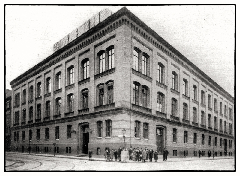
The city pneumatic post was established in the main telegraph office in 1916, and the complete conversion to a center of the Berlin network took place until 1919.
The Berlin pneumatic tube network reached its greatest extent in 1941, with 253.6 kilometers of pneumatic tubes and approximately 150 kilometers of pneumatic tubes. Twenty-two connections of varying lengths originated from the main telegraph office, and another 36 originated from other pneumatic tube offices.
The division of Berlin in 1945 also divided the pneumatic tube network. The main telegraph office, located in the Soviet sector, was the headquarters of the eastern section, which by December 1951 comprised only 43 kilometers of pneumatic tube.
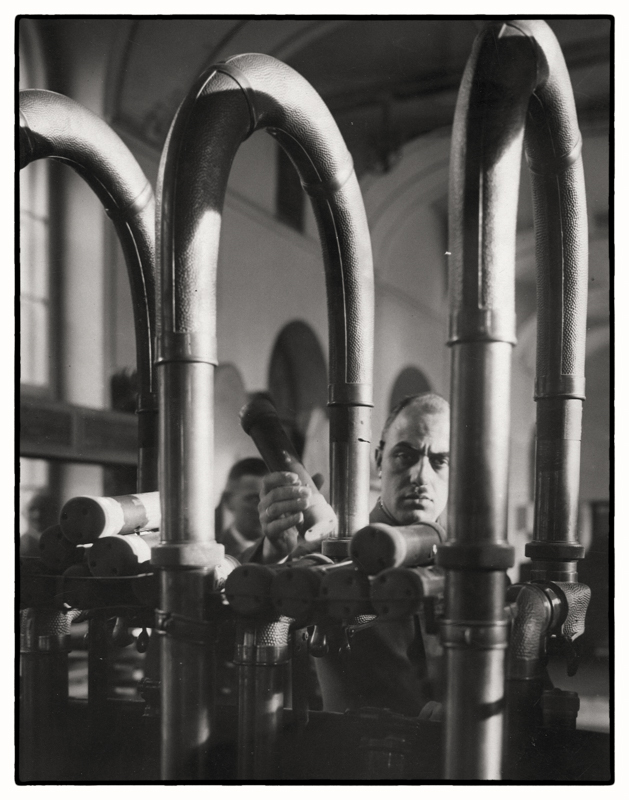
Technical monument
The machine center of the former pneumatic tube system
is a cultural asset of international standing.
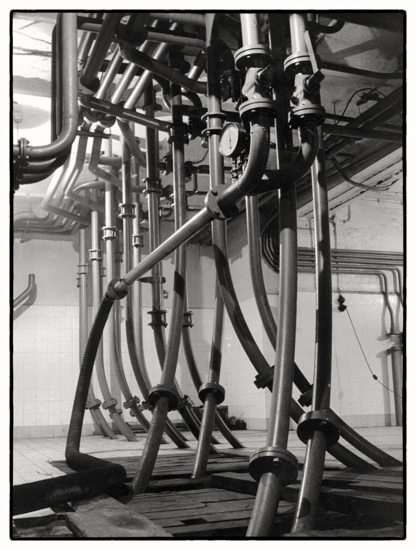
Historical machines
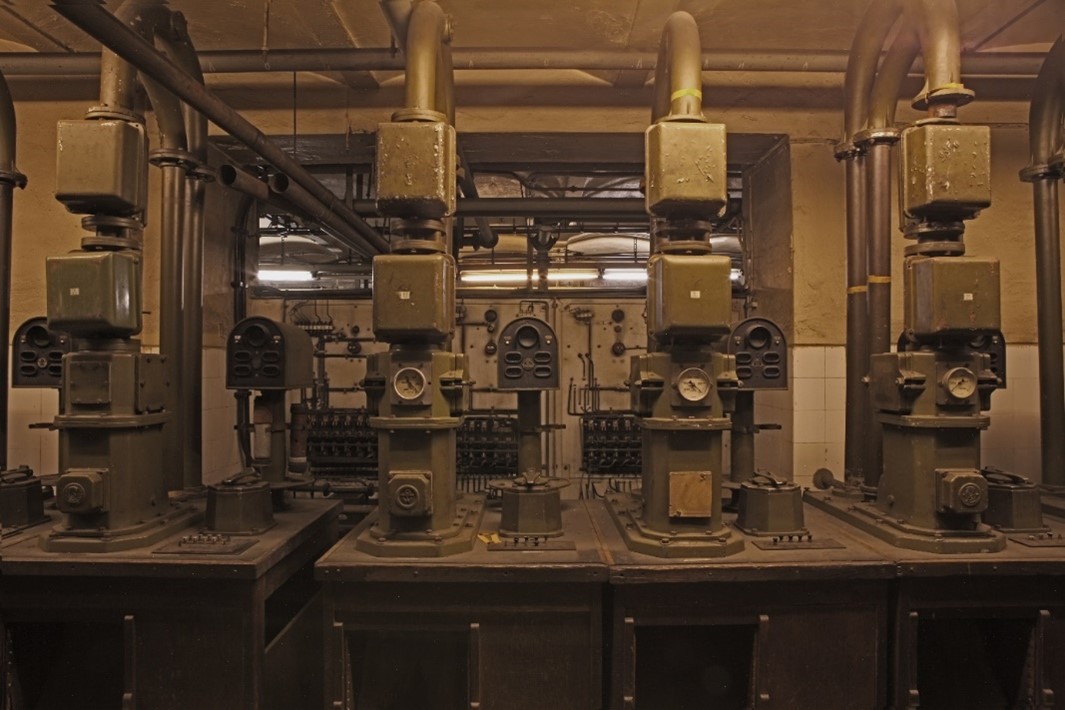
Transmitting and receiving apparatus
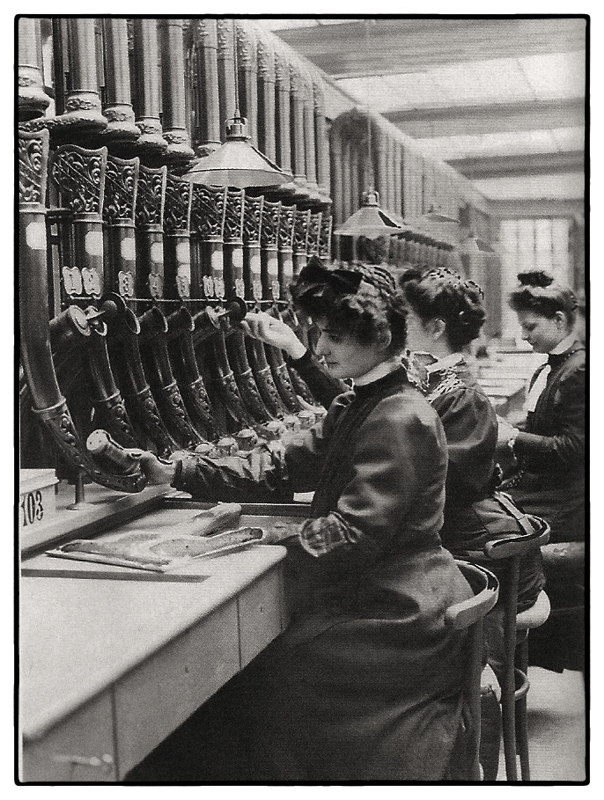
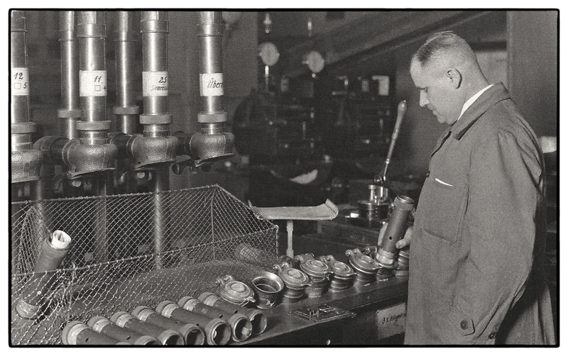
Next to the stairs from the restaurant to the bar are devices that were used after 1920 for sending and receiving pneumatic tubes. The keypad labels allow them to be assigned to routes that were served by the main telegraph office until October 1976.
The devices at the cloakroom are standard products for sending and receiving pneumatic tubes around 1910. They were designated as type 1912 and were in operation on routes with lower transmission volumes until the 1960s.
Deoiler
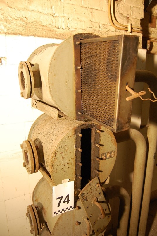
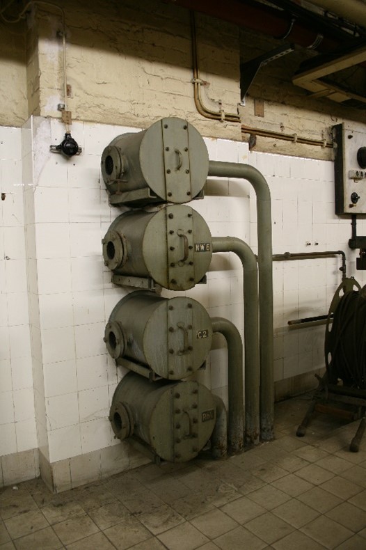
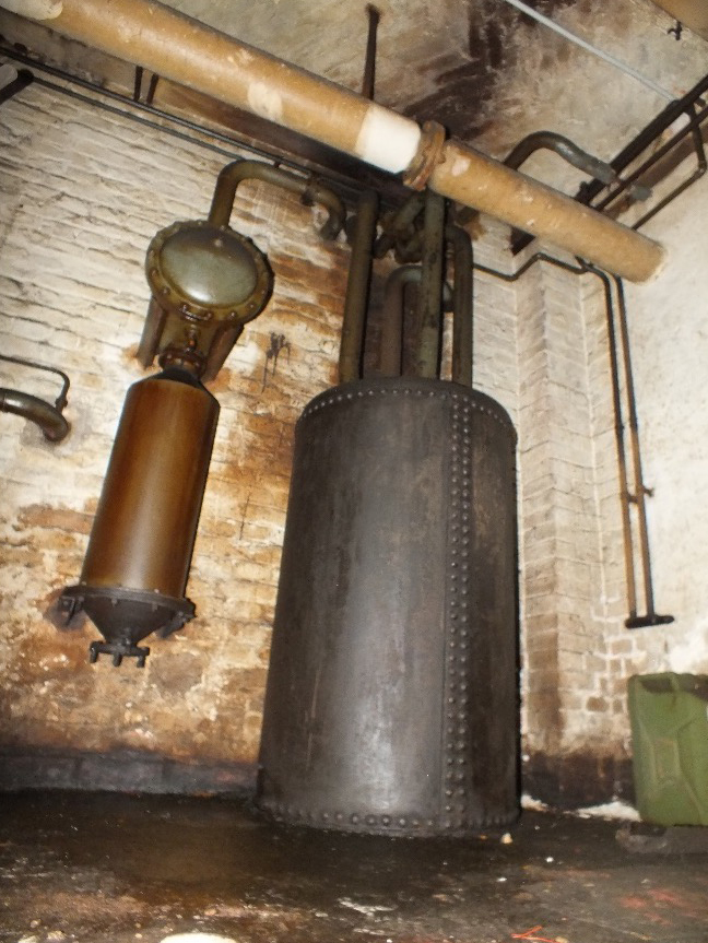
In order to clean the air of grease or oil coming from the compressors for the pneumatic tube system’s compressed air operation, oil separators were installed in the air lines between the compressor and the travel tube or between the pre-cooler and the freezer.
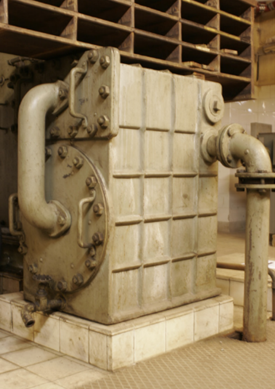
Filter
Filters were used to remove dust from the intake air. These filters were extensions with a larger diameter than the air pipe and incorporated replaceable filter cartridges.
Electrical panel
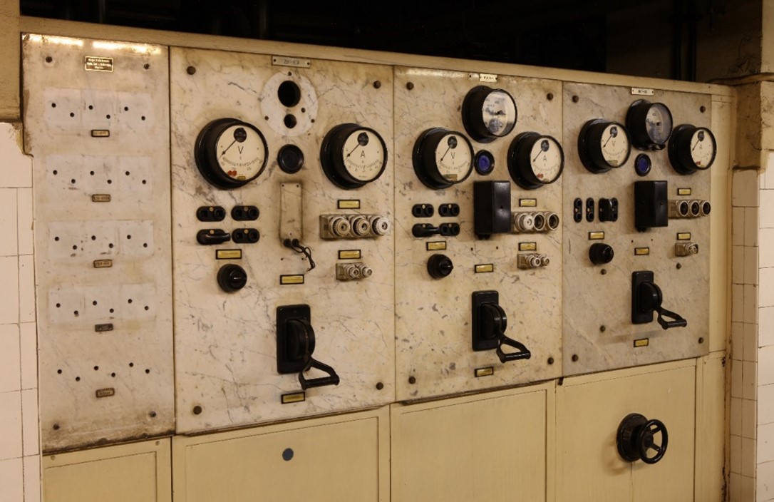
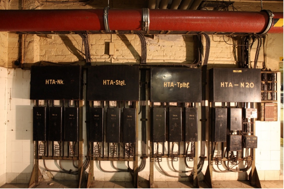
The control panels were used to operate and monitor the compressors. Voltmeters and ammeters were mounted on the panels, with a pressure gauge centrally located between them. Fuses were arranged according to the three phases of the three-phase current. The main switch is located below.
Marble was used for the base plate as an electrical insulating material.
compressor
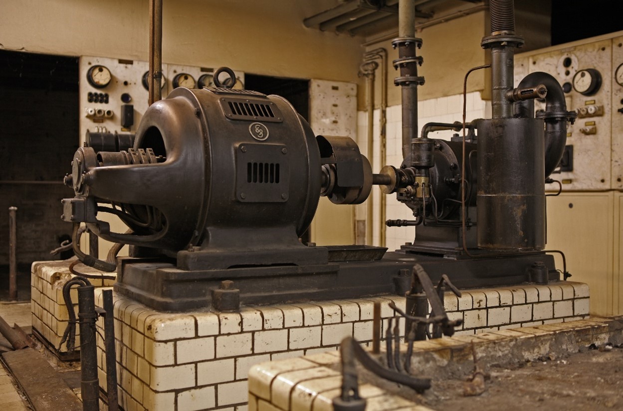
Each compressor also had an electric motor to drive it. Both elements were mounted on a solid cast-iron mounting plate. The plates, in turn, were mounted on a base made of white glazed clinker bricks and lined with concrete.
The compressors provided the suction or compressed air in the pneumatic tube network and were each assigned to a specific route in the city pneumatic tube system.
Today, in the hallway in front of the hotel elevators, stands the only remaining rotary compressor from the time the main telegraph office was built, still filled with water. Its base is anchored directly to the ground due to the rigid water pipes and was formerly only “sprung” by a thick cork board.
All other compressors on the city pneumatic tube system have finned housings for cooling. This type of cooling was state of the art until the pneumatic tube system was shut down. Their bases could be placed on dampers to prevent vibration transmission.
A special feature is the green-coated compressor in the bar area, which was only manufactured in 1960 and was again water-cooled.
In the “Kutscherhof” and below the stairs to the restaurant are three compressors with rotary lobe blowers. They were connected in series and used for all or a large part of the former pneumatic tube system.
Line control
The line control system provided connections to the switches in the travel tubes located on the road, to machines such as transmitters and receivers or compressors in small pneumatic tube offices, and to the control panels within the main telegraph office.
Expansion tank
The air tank (air chamber) was used to absorb fluctuating delivery rates of the compressed or suction air when air consumption in the network changed or when the compressor performance fluctuated.
pneumatic tube carriers
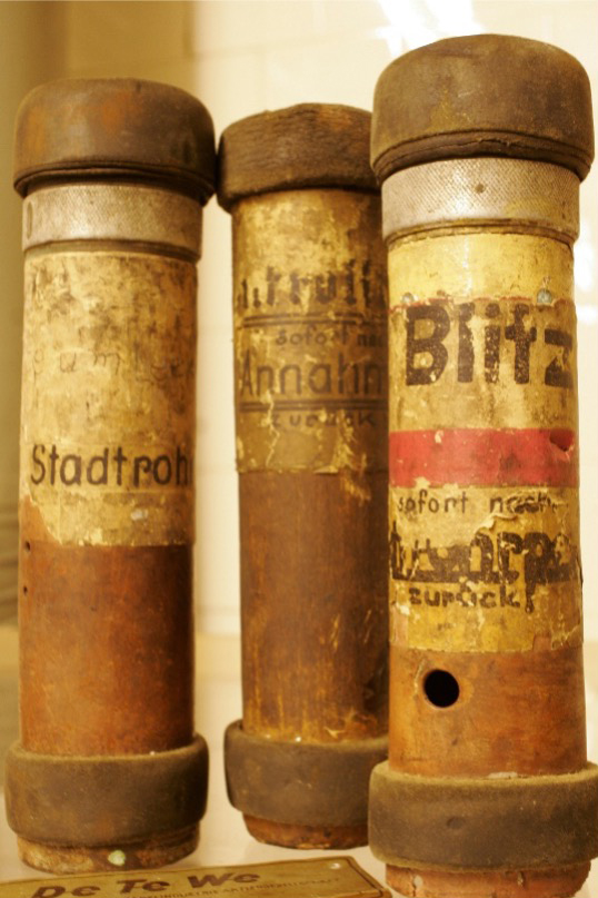
They were used as transport containers for postcards, telegrams, or letters. Initially, they were made of sheet steel and fitted with leather caps and seals; later, lighter aluminum cans with rubber-fabric caps and driver disks were used. The standard outer diameter was 65 millimeters.
For the city pneumatic tube system, which traveled long distances and at speeds of up to 15 meters per second, the boxes were sealed all around. For the residential pneumatic tube system, which traveled short distances and at speeds of between 8 and 10 meters per second, the boxes could remain open at the back.
For marking and later for automatic control of switches, boxes were equipped with number rings or contact rings.
Cable termination rack
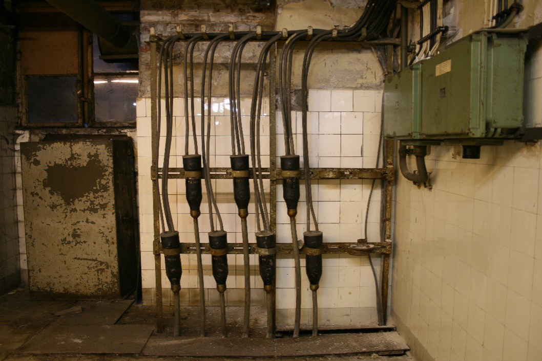
At this frame, the bundled signal cables used to control switches or machine stations of small pneumatic tube offices entered the main telegraph office and were divided for connection to the power distributors or line switches.
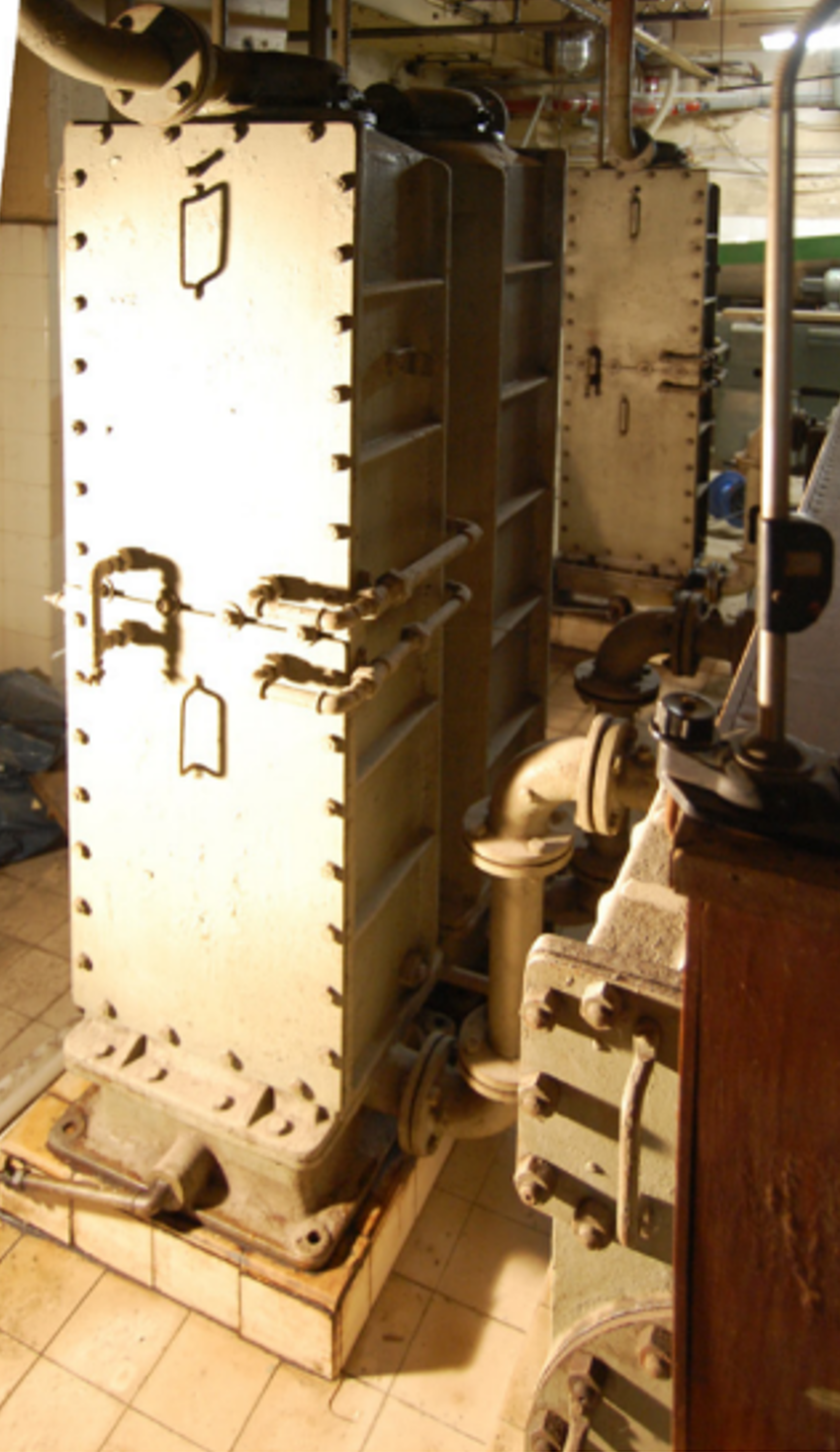
Precooler
Precoolers were used to dehumidify the air through condensation. Water was used for cooling. The pressurized air, which reached approximately 60 °C, was cooled to 20 °C using the water. The precooler was able to dehumidify down to 9 g of water per kg of air.
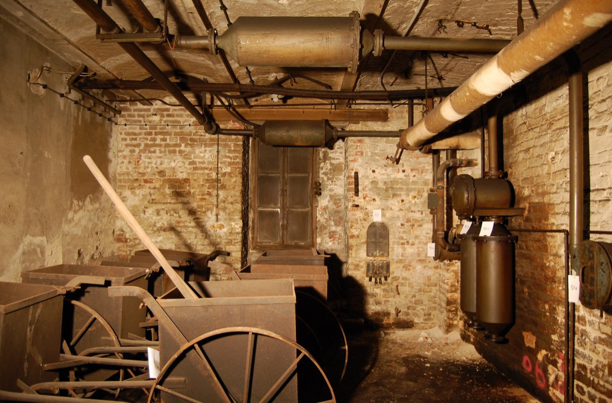
silencer
The reflection silencers were used to reduce the noise generated by the compressors or by the flowing air. This was achieved by combining the cross-sections on one side and expanding them on the other side of a built-in baffle. The silencers are usually installed in the air ducts immediately after the compressors.
Overload switch
The function of this electrical component is only speculated. It cannot be deduced from any marking or labeling. The three original circuit breakers were assigned to specific control panels and thus to specific compressors. They replaced the function of the sub-distribution boards equipped with fuses.
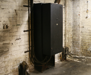
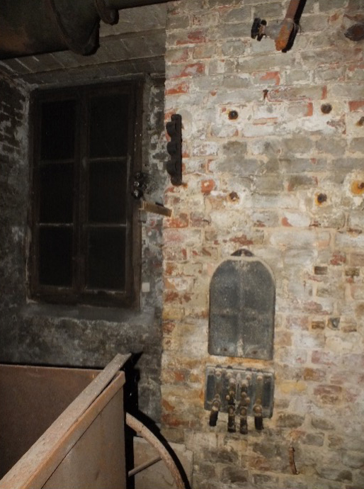
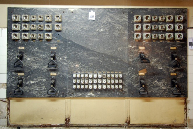
Subdistribution
The oldest preserved sub-distribution board still shows the license plate “BEW” of the Berliner Elektrizitätswerke (Berlin Electricity Works) in the top right corner.
The three-part sub-distribution board is a unique feature in the machine center, both due to its size and its construction, consisting of three slabs of black marble. Two of the marble slabs are even carved from the stone in such a way that the veins run across both slabs.
In contrast to most switchboards, it can be dated to the construction period of the new main telegraph office between 1910 and 1916.
Signal boards
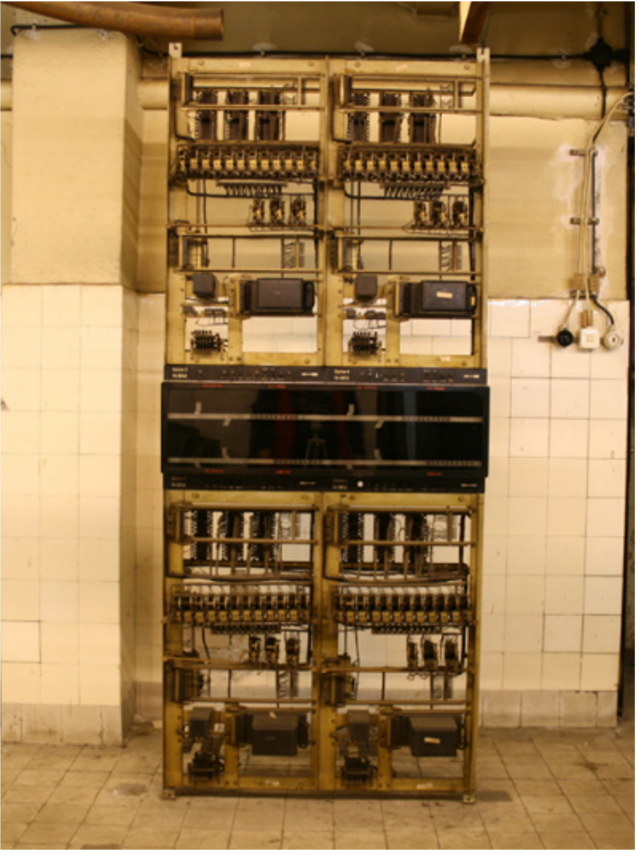
The signal panels indicated the operational status of the pneumatic tube network and thus served as a monitoring system. Their original location was in a separate room on the ground floor. The displays on the more than 27 signal panels showed the number of pneumatic tube carriers, their position along the line, and their entry and exit.
driver
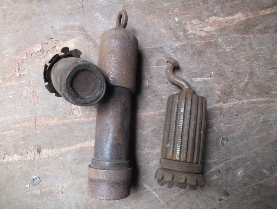
The wooden or steel drivers were used to dispatch “trains” of pneumatic tube carriers. These consisted of three to five carriers, although up to ten were technically possible. The drivers are heavier, often have a larger diameter, and are always shorter than the carriers.
freezer
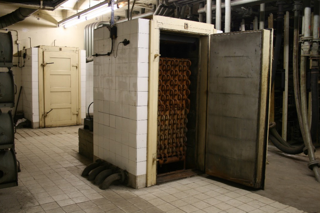
Previously, two freezers were used to dehumidify the air; they are connected to a pre-cooler via de-oilers.
A refrigerant was used for cooling. The air flowing through the freezer was cooled to 10 °C. The freezer was able to dehumidify down to 6 g of water per kg of air.
cooler
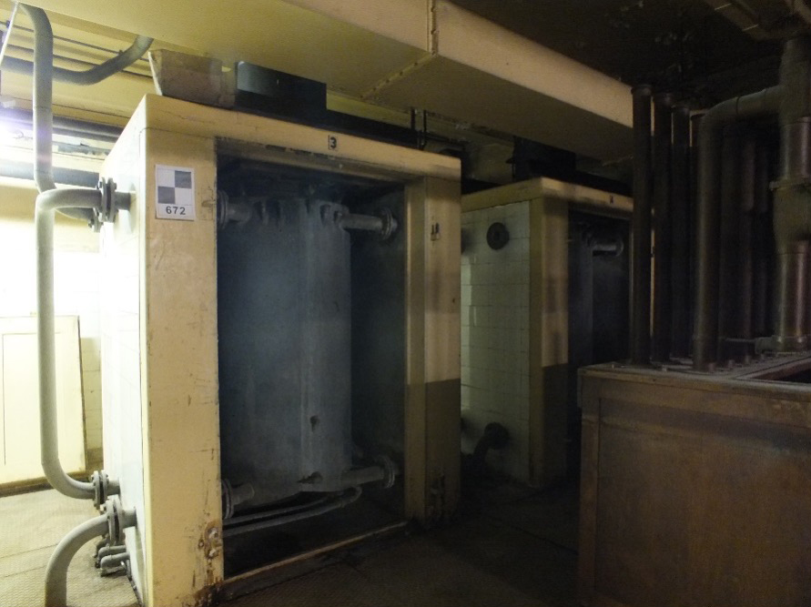
The two coolers at that time also served to dehumidify the air. The air, drawn in through filters from the room, was fed into the coolers at the bottom and, on its way up, passed the previously existing cooling fins, where the moisture in the air condensed as condensate.
The coolers may have been technically upgraded and most recently operated with a refrigerant. Unlike the freezers, they are not connected to any other air treatment equipment, as they were only integrated into short sections of the city’s pneumatic tube system with reversing operation.
